

Classic Mini Cooper rockers, push rods and more!
 Shop Rocker Assemblies & Components
Shop Pushrods
When you are trying to build a motor to get the ultimate of performance you often will also optimize the life expectancy of the entire assembly. One such area centers around the rocker assembly. In general the rockers are part of the process that translates the lobe of the rotating camshaft to the vertical deflection needed to open the valves on the cylinder head. On a stock Mini the rocker is also designed to slightly amplify the movement with a rocker that is slightly longer on the valve side of the rocker than on the pushrod side; ie. For every .1” the pushrod is moved, the valve is deflected .125”. As the pushrod rides up on the cam lobe the vertical movement is translated to the rocker that pushes down on the valve.
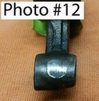 If we consider this rocker action we note that the deflection of the rocker really results in an arc of movement on either end of the rocker. At one end the pushrod in addition to moving up and down in the block it is also moving front to back in the hole. At the valve end of the rocker the same kind of thing is happening except to an even further degree as it is actually moving further due to the 1.25 ratio (or 1.5 in the case of performance rockers). At the pushrod end we find a nicely designed ball and socket that provides a pretty consistent pivot point even while allowing fore and aft movement. On the valve side the contact surface is not as sophisticated. The end of the rocker that strikes the top of the valve has a face on the tip with a consistent arc that has an effective different length depending on where the arc of the tip first strikes the tip of the valve. Any rockers with even a light amount of wear on this pad (Photo #12) can result in much degraded performance.
 Rocker geometry in our vintage motors is a series of compromises and a lot has been written on the numerous, very complex factors that are in play with rockers. They indeed can have a very dramatic impact on performance. We often spend a lot of time & money picking a camshaft that has been designed and ground within extremely tight tolerances. We then set the camshaft timing to within a degree or so of the optimum. And then we throw on a set of rockers and say all is good?? Rocker geometry can not only change valve lift but even camshaft timing itself. To make matters worse it could be different from one rocker to the next!
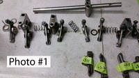
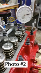
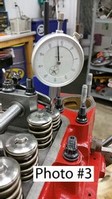
The first step is to measure each of the rockers (Photo #1) in a manner that only tests the rocker and avoids all the other variables such as the height of each valve, wear on the tip of the valve, and depth of the valve in the valve seat. The easiest way to do it is to strip a rocker assembly down to two pedestals only and put them back on the head with one pushrod in number one position. With the adjustment backed all the way off you can typically slide each rocker on and off without having to remove the shaft. As shown in photo #2 you then simply place the dial indicator on the spring retainer and rotate the engine thru a cycle to find total valve lift.
The
 objective of this part of the setup is to simply compare rocker to rocker. Absolute numbers are not as critical as repeatable ones. Set the valve clearance to zero to improve consistency. Move the indicator away as if to change the rocker a couple times and measure the same rocker to help insure you have a consistent procedure before testing the rest of the rockers. In the best of times, you would have enough extra rockers to match up a consistent set.
 The next step in the process is to establish the center line of the rocker pivot point in relationship to the pushrod on one end and the valve tip on the other. While often debated we have concluded that the optimal vertical location is such that the valve tip, the pivot point at the pushrod, and the center of the rocker be as close to horizontal as possible when the valve has
 reached its half open position. Assuming you first have a set of rockers that produce the same valve lift within .010” you can again use the dial indicator on one valve spring retainer and cycle the engine until you open the valve 50% of the total. Once this is set, the only practical step is to use a straight edge (Photo #9) to eyeball the tip and pushrod ends of the rocker with the center line of the shaft. Typically the need will be to raise the center line of the shaft. This is done in increments by adding shims/spacers under each of the pedestals- very much a trial and error process. In rare occasions it would be necessary to have the pedestals machined shorter. If this is the case- you can then use shims to sneak back to the correct height. PS- the pedestal spacers are available in .030, .060 or .090 thickness (Photo #13).
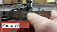
The final step in the process is multifaceted. As the ends of the rockers move in an arc, they also go up & down. The pushrod holes in the head are extremely small (and poorly aligned) and it is critical that you closely watch that the pushrod does not hit on the side of the head as it goes up and down. (Photo #5) The location of the rocker on the shaft horizontally is easy enough to set with shims. The real challenge is to have close-to-center contact of the
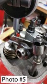 rocker on the tip of the valve, while still not having the pushrod rub against the block/head as it goes up and down. Each and every rocker will have to be shimmed differently as hole location in the head as well as pedestal location is not very precise.
A few final cautions to be observed during final assembly; be sure the front of the rocker pedestal spacers are not interfering with the bottom edge of the springs. Be sure to cycle the engine a number of times before finally torqueing the head bolts to be sure that everything is seated in place. Be sure to set the valve rocker clearance per the camshaft manufacturer specs before starting the motor.


